1. Data and number systems;Binary, Octal and Hexa decimal representation and their conversions ;BCD,ASCII, EBDIC, Gray codes and their conversions; Signed binary number representation with 1’s and 2’s complement methods,
Binary arithmetic. Venn diagram, Boolean algebra; Various Logic gates-their truth tables and circuits; Representation in SOP and POS forms; Minimization of logic expressions by algebraic method, Kmap method
🧮 1. Data and Number Systems (डेटा और संख्या प्रणालियाँ)
डेटा को कंप्यूटर में बाइनरी (0 और 1) के रूप में स्टोर और प्रोसेस किया जाता है।
🔢 Binary, Octal और Hexadecimal – प्रस्तुति और कन्वर्ज़न
| प्रणाली | बेस | अंकों का प्रयोग |
|---|---|---|
| Binary (बाइनरी) | 2 | 0, 1 |
| Octal (ऑक्टल) | 8 | 0–7 |
| Hexadecimal (हेक्साडेसिमल) | 16 | 0–9, A–F |
✅ Conversion:
- Binary → Decimal
- Decimal → Binary
- Binary ↔ Octal: हर 3 बिट = 1 ऑक्टल अंक
- Binary ↔ Hexadecimal: हर 4 बिट = 1 हेक्सा अंक
🔢 2. Codes and Representations
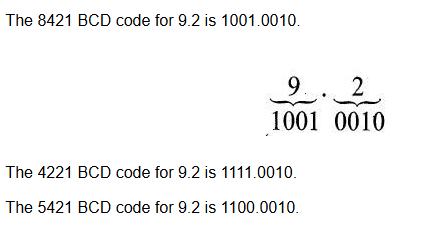
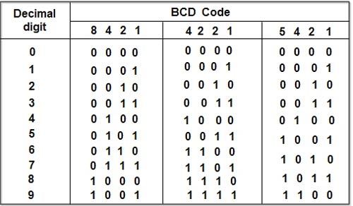
📦 BCD (Binary Coded Decimal):
- हर दशमलव अंक (0–9) को 4 बिट्स में दर्शाया जाता है।
| Decimal | BCD |
|---|---|
| 5 | 0101 |
| 9 | 1001 |
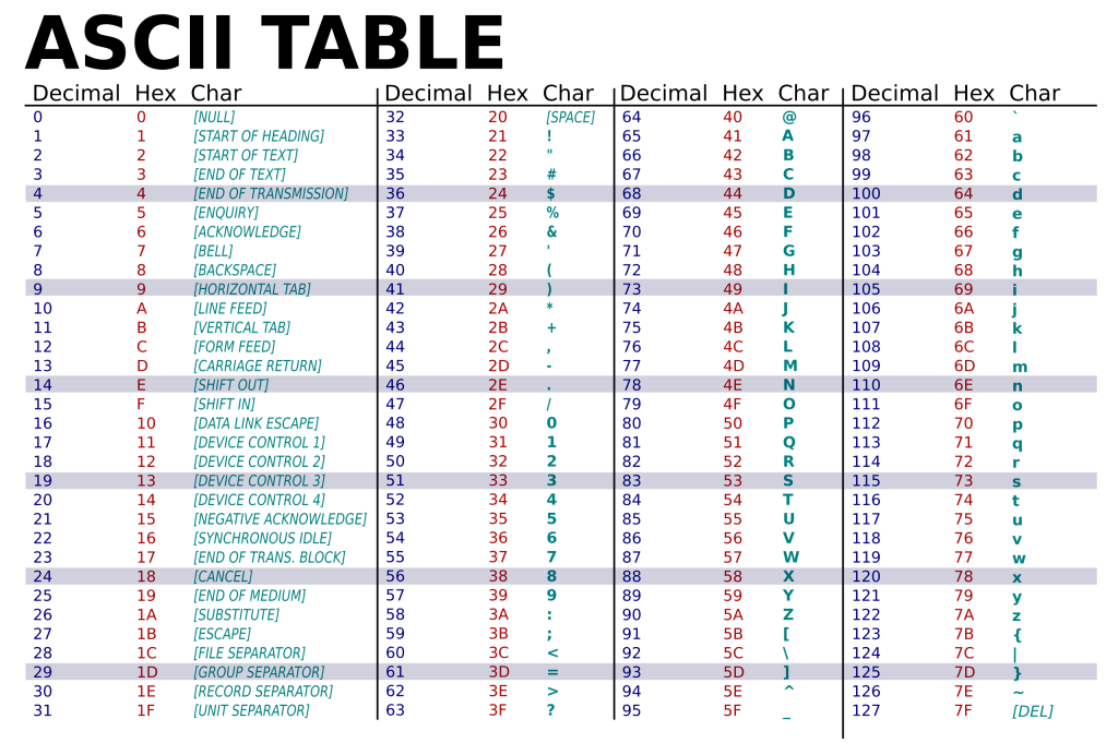
🔤 ASCII (American Standard Code for Information Interchange):
- हर कैरेक्टर को 7-बिट बाइनरी कोड में दर्शाता है।
| Character | ASCII (Decimal) | Binary |
|---|---|---|
| A | 65 | 1000001 |
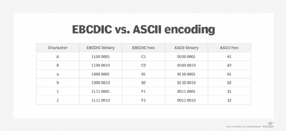
🖨️ EBCDIC (Extended Binary Coded Decimal Interchange Code):
- IBM द्वारा प्रयोग किया गया 8-बिट कोड
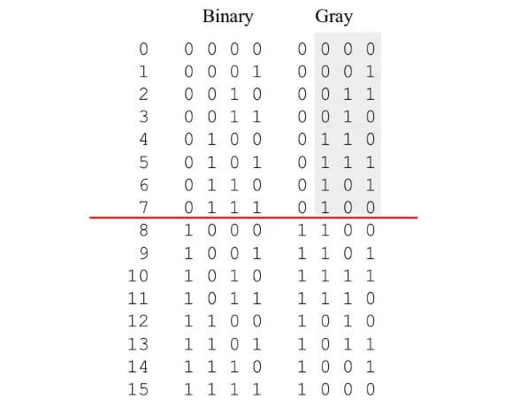
⚙️ Gray Code:
- दो क्रमागत कोड्स में केवल एक बिट का अंतर होता है।
- उपयोग: एरर फ्री डेटा ट्रांसफर (जैसे रोटरी एनकोडर में)
✅ Binary ↔ Gray Code Conversion संभव है
➕➖ 3. Signed Binary Number Representation
✅ दो तरीके:
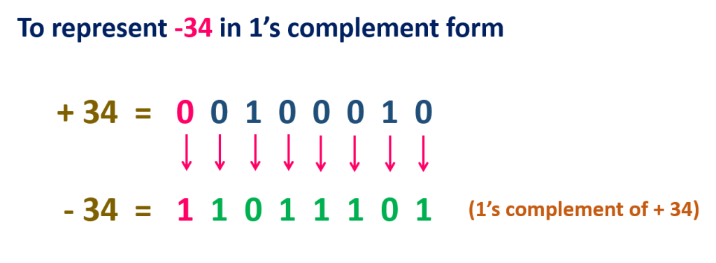
1️⃣ 1’s Complement Method
- किसी संख्या के सभी बिट्स को उलटा कर दो (1 → 0, 0 → 1)
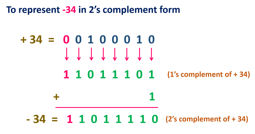
2️⃣ 2’s Complement Method
- 1’s Complement + 1 = 2’s Complement
- उपयोग: नेगेटिव संख्याओं का प्रतिनिधित्व करने के लिए
➗ 4. Binary Arithmetic (बाइनरी गणित)
| ऑपरेशन | नियम |
|---|---|
| Addition | 0+0=0, 1+0=1, 1+1=10 |
| Subtraction | 0−0=0, 1−0=1, 1−1=0 |
| Multiplication | 0×0=0, 1×1=1 |
| Division | बाइनरी में Long Division जैसा |
🔁 5. Venn Diagram (वेंन चित्र)
- सेट्स और लॉजिक को विज़ुअली दर्शाने का तरीका
- Boolean एक्सप्रेशन्स को विज़ुअल रूप में दर्शाने के लिए प्रयोग होता है
🧠 6. Boolean Algebra (बूलियन बीजगणित)
- लॉजिक ऑपरेशन्स का गणितीय विश्लेषण
- सिर्फ 0 और 1 पर आधारित
✅ Laws:
- AND, OR, NOT के नियम
- Identity, Null, Idempotent, Involution, Absorption, Demorgan’s Theorem आदि
🔌 7. Logic Gates (लॉजिक गेट्स)
| Gate | Symbol | Truth Table |
|---|---|---|
| AND | A·B | 1 तभी जब दोनों इनपुट 1 |
| OR | A+B | कोई एक इनपुट 1 हो तो आउटपुट 1 |
| NOT | A̅ | इनपुट का उल्टा |
| NAND | (A·B)̅ | AND का NOT |
| NOR | (A+B)̅ | OR का NOT |
| XOR | A⊕B | जब इनपुट अलग हों तब 1 |
| XNOR | A⊙B | जब इनपुट समान हों तब 1 |
🔤 8. SOP & POS Forms
🧾 SOP (Sum of Products):
- 1 वाले आउटपुट्स के लिए टर्म्स का योग (OR)
- जैसे: F = A·B + A̅·B
🧾 POS (Product of Sums):
- 0 वाले आउटपुट्स के लिए टर्म्स का गुणन (AND)
- जैसे: F = (A + B)·(A̅ + B)
➖ 9. Minimization of Boolean Expression
🧮 (a) Algebraic Method:
- बूलियन नियमों का प्रयोग करके सिंप्लिफाइ करना
🗺️ (b) Karnaugh Map (K-Map Method):
- विज़ुअल ग्रिड द्वारा एक्सप्रेशन को सिंप्लिफाइ करना
- SOP या POS को मिनिमाइज़ करने का आसान तरीका
✔ 2, 3, 4 व 5 Variables तक के K-map प्रयोग होते हैं
📋 Quick Summary (संक्षेप सार)
| विषय | मुख्य बिंदु |
|---|---|
| संख्या प्रणाली | Binary, Octal, Hexadecimal और उनके कन्वर्ज़न |
| कोड्स | BCD, ASCII, EBCDIC, Gray Code |
| Signed Numbers | 1’s और 2’s Complement |
| बाइनरी अंकगणित | जोड़, घटाव, गुणा, भाग |
| Boolean Algebra | लॉजिक के नियम और समीकरण |
| Logic Gates | AND, OR, NOT, XOR आदि |
| SOP/POS | एक्सप्रेशन फॉर्म्स |
| Minimization | K-map और Algebraic तरीके |
Here’s a brief discussion of each topic mentioned in the text:
1. Data and Number Systems
- A system to represent numbers in different bases, including Binary (Base-2), Octal (Base-8), and Hexadecimal (Base-16).
- Each system has its applications in digital electronics and computing.
2. Binary, Octal, and Hexadecimal Representation & Conversion
- Binary: Uses only 0s and 1s; fundamental for digital circuits.
- Octal & Hexadecimal: More compact representations of binary numbers.
- Conversions: Direct conversion methods between Decimal, Binary, Octal, and Hex.
3. BCD, ASCII, EBCDIC, and Gray Codes
- BCD (Binary Coded Decimal): Each decimal digit is separately represented in binary.
- ASCII (American Standard Code for Information Interchange): Standard encoding scheme for text.
- EBCDIC (Extended Binary Coded Decimal Interchange Code): Similar to ASCII, used in older mainframes.
- Gray Code: Used to minimize errors in digital circuits, particularly in rotary encoders.
4. Signed Binary Representation & Complement Methods
- 1’s Complement: Flip the bits to represent negative numbers.
- 2’s Complement: Flip bits and add 1; commonly used for binary arithmetic.
5. Binary Arithmetic
- Operations like addition, subtraction, multiplication, and division performed on binary numbers.
- Overflow conditions must be checked during arithmetic operations.
6. Venn Diagram & Boolean Algebra
- Venn Diagram: Graphical representation of set operations and Boolean expressions.
- Boolean Algebra: Mathematical approach to logic circuits, governed by AND, OR, NOT, and De Morgan’s Theorems.
7. Logic Gates, Truth Tables & Circuits
- Basic Gates: AND, OR, NOT.
- Universal Gates: NAND, NOR (can implement any circuit).
- Special Gates: XOR, XNOR (used in parity checks and circuits).
- Truth Tables: Define the behavior of logic gates.
- Circuits: Combinations of logic gates to perform specific operations.
8. SOP (Sum of Products) & POS (Product of Sums) Representation
- SOP (Sum of Products): Logical OR of multiple AND terms.
- POS (Product of Sums): Logical AND of multiple OR terms.
- Used in designing logic circuits.
9. Minimization of Logic Expressions
- Algebraic Method: Applying Boolean laws to simplify expressions.
- K-Map (Karnaugh Map) Method: A visual way to minimize Boolean functions and reduce circuit complexity.
These concepts are fundamental in digital logic design, essential for understanding computer architecture, digital circuits, and embedded systems. Let me know if you need further elaboration! 🚀
2. Combinational circuits-Adder and Subtractor circuits; Applications and circuits of Encoder ,Decoder, Comparator ,Multiplexer, De-Multiplexe rand Parity Generator. Memory Systems: RAM ,ROM, EPROM, EEROM, Design of combinational circuits-using ROM, Programming logic devices and gate arrays. (PLAs and PLDs)
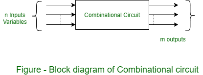
🧮 Combinational Circuits (समायोज्य परिपथ)
📌 परिभाषा:
- ये ऐसे डिजिटल सर्किट होते हैं जिनका आउटपुट केवल वर्तमान इनपुट पर निर्भर करता है, ना कि पिछले किसी स्टेट पर।
- इनमें मेमोरी नहीं होती।
🔢 Adder और Subtractor Circuits
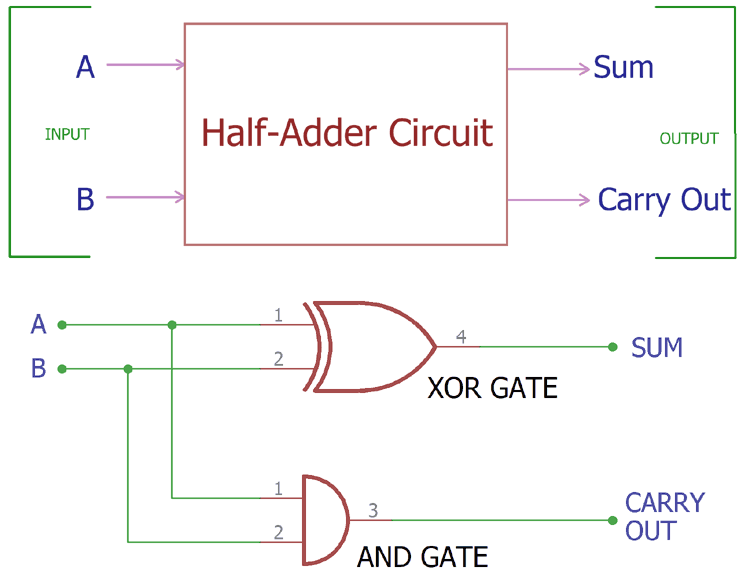
➕ 1. Half Adder (हाफ ऐडर):
- दो बिट्स को जोड़ता है (A और B)
- आउटपुट:
- Sum = A ⊕ B
- Carry = A · B
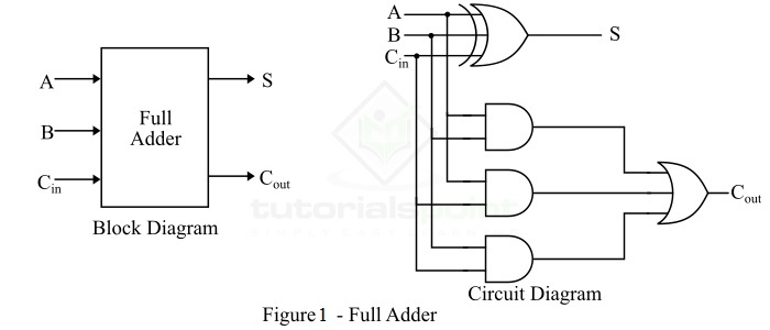
➕➕ 2. Full Adder (फुल ऐडर):
- तीन इनपुट जोड़ता है: A, B और Carry-in
- आउटपुट:
- Sum = A ⊕ B ⊕ Cin
- Carry = AB + BCin + ACin
➖ 3. Half Subtractor:
- दो बिट्स को घटाता है
- आउटपुट:
- Difference = A ⊕ B
- Borrow = A̅ · B
➖➖ 4. Full Subtractor:
- A – B – Bin (Borrow in) करता है
💡 Encoder और Decoder
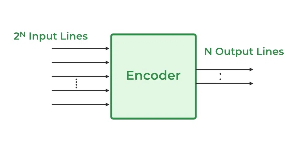
🔢 Encoder:
- 2ⁿ इनपुट को n-बिट आउटपुट में कन्वर्ट करता है
- उदाहरण: 8-to-3 Encoder
- अगर इनपुट D5 = 1 है, तो आउटपुट = 101
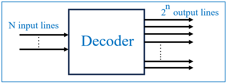
🔄 Decoder:
- n-बिट इनपुट को 2ⁿ आउटपुट लाइन्स में बदलता है
- उदाहरण: 3-to-8 Decoder
- इनपुट 101 = आउटपुट लाइन D5 को 1 करेगा
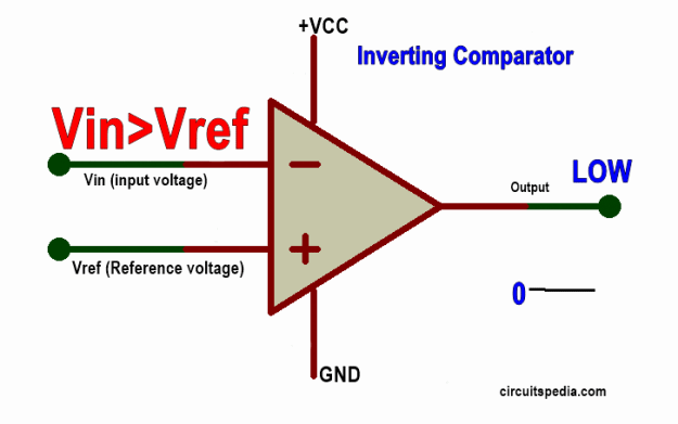
📏 Comparator (तुलनित्र):
- दो बाइनरी नंबरों की तुलना करता है
- बताता है: A > B, A = B, A < B
- उपयोग: सॉर्टिंग, सेलेक्शन लॉजिक आदि में
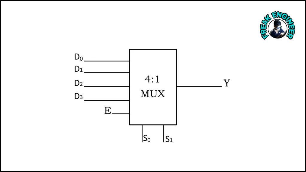
🎚️ Multiplexer (MUX):
- कई इनपुट से एक सिंगल आउटपुट चुनता है
- उदाहरण: 4-to-1 MUX → 4 इनपुट, 2 सेलेक्ट लाइन्स
- आउटपुट: S0 और S1 से तय होता है कौन सा इनपुट पास होगा
⛓️ Circuit Symbol:
I0 I1 I2 I3
  \ | | /
   \| |/
    MUX --- OUT
   /  \
 S0   S1
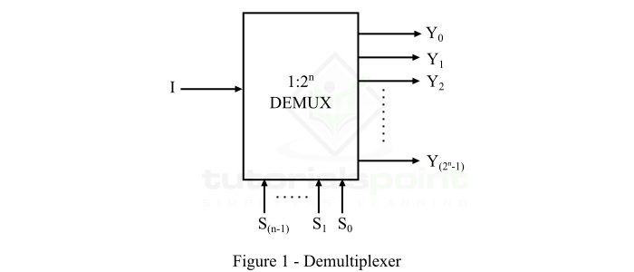
🔀 De-Multiplexer (DeMUX):
- एक इनपुट को कई आउटपुट में बांटता है
- उदाहरण: 1-to-4 DeMUX
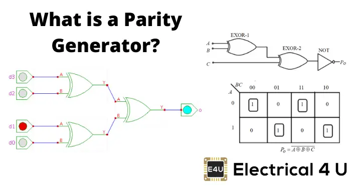
✅ Parity Generator:
- डेटा ट्रांसमिशन में एरर डिटेक्शन के लिए प्रयोग होता है
- Odd/Even parity बिट जोड़ता है ताकि कुल 1’s की संख्या सम/विषम हो जाए
🧠 Memory Systems (मेमोरी प्रणालियाँ)
| प्रकार | विवरण |
|---|---|
| RAM | Random Access Memory: Temporary storage, volatile |
| ROM | Read Only Memory: स्थायी डेटा |
| EPROM | Erasable Programmable ROM: UV Light से मिटाया जाता है |
| EEPROM | Electrically Erasable Programmable ROM: इलेक्ट्रिकली मिटाया जाता है |
🛠️ Design of Combinational Circuits using ROM
- ROM को Truth Table के अनुसार प्रोग्राम करके Combinational Circuit डिजाइन किया जा सकता है
- यह LUT (Lookup Table) की तरह काम करता है
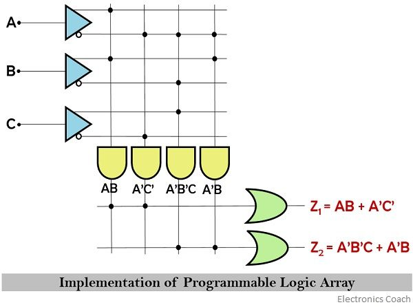
🔲 Programming Logic Devices (PLDs)
✅ PLAs (Programmable Logic Arrays):
- Pre-defined AND और OR arrays होती हैं
- Programmable होती हैं → Custom Logic Design संभव
✅ PALs (Programmable Array Logic):
- Fixed OR Array + Programmable AND Array
- कम जटिलता, तेज़ गति
🔳 Gate Arrays (GAs):
- पहले से डिजाइन किए गए Logic Gates का Group
- Programmable होते हैं जैसे FPGA (Field Programmable Gate Arrays)
📋 Quick Summary (संक्षेप सार)
| टॉपिक | मुख्य बिंदु |
|---|---|
| Adder/Subtractor | बाइनरी जोड़/घटाव (Half/Full) |
| Encoder/Decoder | Input ↔ Output लाइन कन्वर्ज़न |
| Comparator | A > B / A = B / A < B |
| MUX/DeMUX | मल्टीपल इनपुट/आउटपुट हैंडलिंग |
| Parity Generator | Error Detection के लिए |
| Memory | RAM, ROM, EPROM, EEPROM |
| ROM-based Design | Truth table को ROM में स्टोर करना |
| PLAs/PLDs | कस्टम लॉजिक सर्किट के लिए प्रयोग |
1. Combinational Circuits
- Adder Circuits: Perform binary addition.
- Half Adder: Adds two binary digits, producing sum and carry.
- Full Adder: Adds three binary digits (two inputs and a carry).
- Subtractor Circuits: Perform binary subtraction.
- Half Subtractor: Subtracts two bits and provides difference & borrow.
- Full Subtractor: Handles three bits (two inputs and a borrow).
2. Applications & Circuits
- Encoder: Converts multiple input lines into a coded output.
- Decoder: Converts a coded input into multiple output lines.
- Comparator: Compares two binary numbers and determines equality, greater, or lesser conditions.
- Multiplexer (MUX): Selects one input from many based on select lines.
- Demultiplexer (DEMUX): Takes a single input and routes it to multiple outputs.
- Parity Generator: Used for error detection in data transmission.
In computer networks, parity refers to a simple form of error detection using a parity bit. This extra bit is added to a binary data sequence to ensure the number of “1” bits is either always even (even parity) or always odd (odd parity).
3. Memory Systems
- RAM (Random Access Memory): Volatile memory used for temporary storage.
- ROM (Read-Only Memory): Non-volatile memory used for permanent storage.
- EPROM (Erasable Programmable ROM): Can be erased using UV light and reprogrammed.
- EEPROM (Electrically Erasable Programmable ROM): Can be erased and rewritten electrically.
4. Design of Combinational Circuits Using ROM
- ROM can be used to implement combinational logic functions by storing truth tables.
- Helps in customized logic circuit design without using separate logic gates.
5. Programmable Logic Devices (PLD) & Gate Arrays
- PLAs (Programmable Logic Arrays): Customizable circuits that can implement multiple logic functions.
- PLDs (Programmable Logic Devices): Generic term for logic circuits that can be programmed after manufacturing.
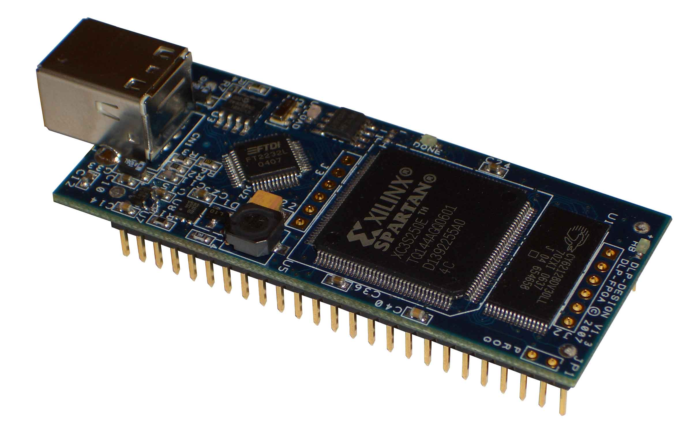
- Gate Arrays: Integrated circuits with predefined logic gates that can be customized for specific applications.
These concepts are widely used in digital electronics, computer architecture, and embedded systems. Let me know if you need more details! 🚀
3. Sequential Circuits-Basic memory element-S-R, J-K,D and T Flip Flops, various types of Registers and counters and their design, Irregular counter, State table and state transition diagram, sequential circuits design methodology.
🔁 Sequential Circuits (अनुक्रमिक परिपथ)
✅ परिभाषा:
Sequential Circuit ऐसे डिजिटल सर्किट होते हैं जिनका आउटपुट वर्तमान इनपुट और पिछले स्टेट (memory) पर निर्भर करता है।
यह Combinational Circuits से अलग होते हैं क्योंकि इनमें मेमोरी एलिमेंट (Flip-Flops) होते हैं।
🧠 Basic Memory Element: Flip-Flop (फ्लिप-फ्लॉप)
Flip-Flop एक 1-bit memory होती है जो डेटा को स्टोर करती है। यह दो स्टेट्स (0 और 1) में रहता है।
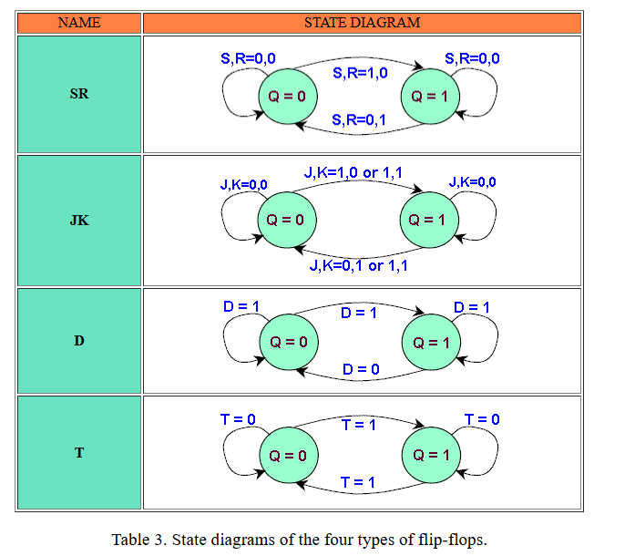
🔄 Types of Flip-Flops:
| प्रकार | फुल फॉर्म | कार्य |
|---|---|---|
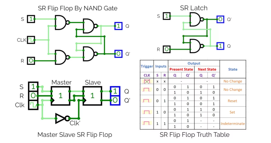
| S-R Flip-Flop | Set-Reset | स्टेट सेट या रिसेट करता है |
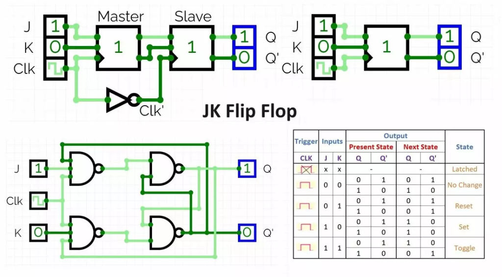
| J-K Flip-Flop | Jack-Kilby | Toggle करता है जब J = K = 1 |
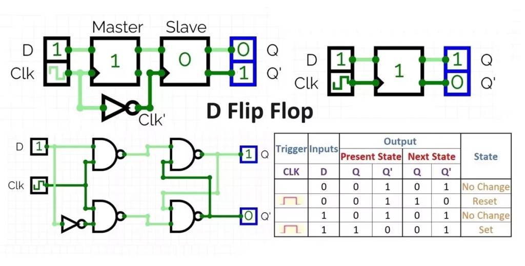
| D Flip-Flop | Data/Delay | इनपुट को एक clock delay के बाद आउटपुट करता है |
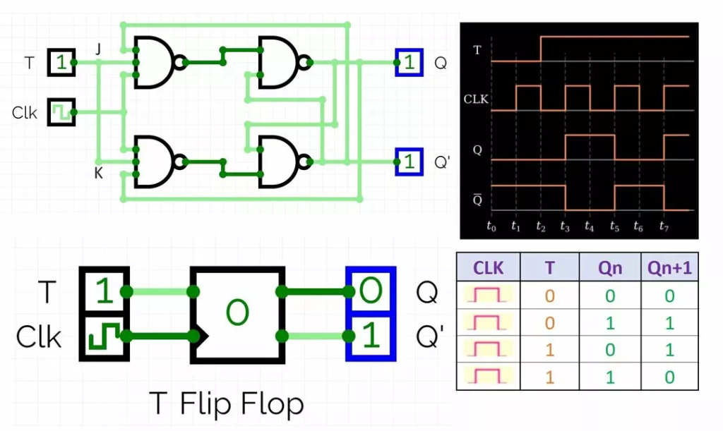
| T Flip-Flop | Toggle | हर clock पर आउटपुट को उलट देता है (toggle) |
📘 Flip-Flop Truth Tables:
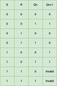
🧾 S-R Flip-Flop:
| S | R | Output Q (Next) |
|---|---|---|
| 0 | 0 | No change |
| 0 | 1 | Reset (0) |
| 1 | 0 | Set (1) |
| 1 | 1 | Invalid (undefined) |
🧾 J-K Flip-Flop:
| J | K | Output Q (Next) |
|---|---|---|
| 0 | 0 | No change |
| 0 | 1 | Reset |
| 1 | 0 | Set |
| 1 | 1 | Toggle |
🧾 D Flip-Flop:
| D | Q(next) |
|---|---|
| 0 | 0 |
| 1 | 1 |
🧾 T Flip-Flop:
| T | Q(next) |
|---|---|
| 0 | No change |
| 1 | Toggle |
🗃️ Registers (रजिस्टर)
✅ परिभाषा:
Registers एक प्रकार का Sequential Circuit होता है जो multiple flip-flops को मिलाकर बनाया जाता है और multi-bit data स्टोर करता है।
🔄 Types of Registers:
- Serial-In Serial-Out (SISO)
- Serial-In Parallel-Out (SIPO)
- Parallel-In Serial-Out (PISO)
- Parallel-In Parallel-Out (PIPO)
👉 Registers का प्रयोग डेटा को ट्रांसफर करने या प्रोसेसिंग के दौरान टेम्पररी स्टोरेज के लिए किया जाता है।
🔢 Counters (काउंटर)
✅ परिभाषा:
Counter एक Sequential Circuit है जो Clock pulses की गिनती करता है।
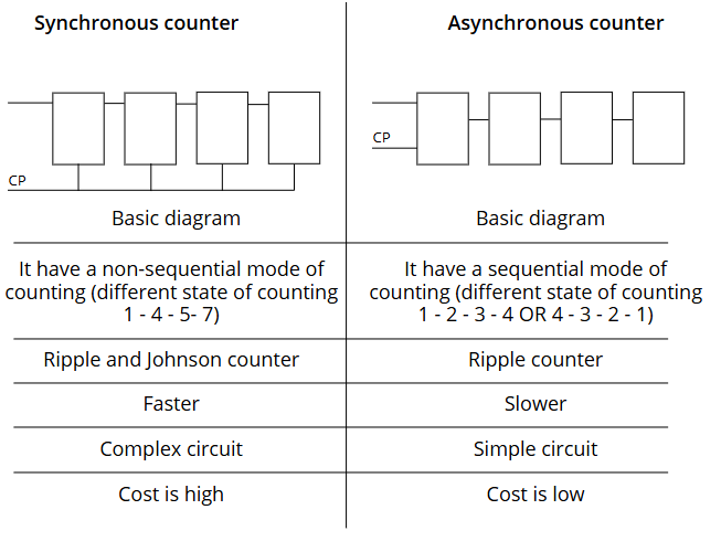
⏳ Types of Counters:
| प्रकार | विवरण |
|---|---|
| Asynchronous Counter | Flip-Flops को एक के बाद एक क्लॉक मिलता है |
| Synchronous Counter | सभी Flip-Flops को एक साथ क्लॉक मिलता है |
| Up Counter | 0 से बढ़ता है (0,1,2…) |
| Down Counter | घटता है (9,8,7…) |
| Up-Down Counter | दोनों दिशा में गिनता है |
| Mod-n Counter | n स्टेट्स तक गिनता है (e.g., Mod-6) |
❓ Irregular Counters:
- ऐसे काउंटर जो नियमित क्रम (0,1,2…) में न गिनकर स्पेशल स्टेट्स में चलते हैं।
- उपयोग: डिजिटल लॉक, सिक्वेंस जेनरेटर
📋 State Table और State Transition Diagram
✅ State Table:
- यह Input, Present State, Next State, और Output को टेबल में दिखाता है।
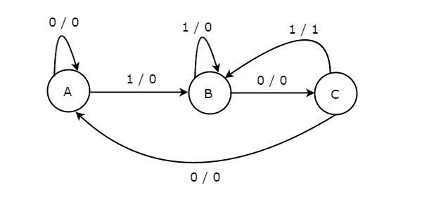
✅ State Transition Diagram:
- यह एक ग्राफिकल तरीका है जिसमें:
- Circle = Current State
- Arrow = Transition (इनपुट पर)
- Label = इनपुट / आउटपुट
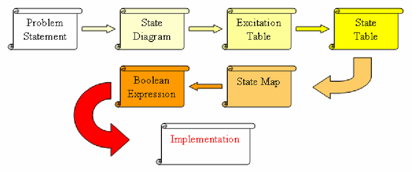
🛠️ Sequential Circuit Design Methodology
स्टेप्स:
- समस्या को समझो (Problem Statement)
- State Diagram बनाओ
- State Table तैयार करो
- State Assignment करो
- Flip-Flop Excitation Table बनाओ
- Boolean Expression निकालो
- Logic Circuit डिजाइन करो
📌 Quick Revision Table:
| टॉपिक | विवरण |
|---|---|
| Flip-Flop | 1-bit memory unit |
| SR, JK, D, T | विभिन्न प्रकार के Flip-Flops |
| Register | Multi-bit स्टोरेज यूनिट |
| Counter | Clock pulses की गिनती |
| State Table | State के इनपुट/आउटपुट को दर्शाता है |
| Transition Diagram | State का ग्राफिकल व्यू |
| Design Methodology | Step-by-step लॉजिक डिजाइन प्रक्रिया |
Here’s a brief discussion of each topic from the image:
1. Sequential Circuits
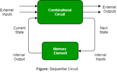
- Unlike combinational circuits, sequential circuits depend on both current inputs and previous states.
- Used in memory storage, timing control, and state machines.
2. Basic Memory Elements (Flip-Flops)
- S-R (Set-Reset) Flip-Flop: Stores a single bit; has Set and Reset inputs.
- J-K Flip-Flop: An improved version of S-R, eliminating invalid states.
- D (Data) Flip-Flop: Transfers input (D) to output on clock pulse; used in registers. A D flip-flop, also known as a data or delay flip-flop.
- T (Toggle) Flip-Flop: Changes state (toggles) with each clock pulse; used in counters.
3. Registers and Counters
- Registers: A group of flip-flops used to store multiple bits of data.
- Types: Shift Registers, Parallel Registers.

- Counters: Sequential circuits used for counting events.
- Synchronous Counters: All flip-flops receive the clock signal simultaneously.
- Asynchronous Counters: Flip-flops are triggered at different times.
4. Irregular Counter
- A non-standard counter that doesn’t follow the typical binary sequence (e.g., ring counter, Johnson counter).
5. State Table & State Transition Diagram
- State Table: Tabular representation of a sequential circuit’s behavior, showing transitions based on inputs.
- State Transition Diagram: A graphical representation of state changes in a sequential circuit.
6. Sequential Circuit Design Methodology
- Steps for designing sequential circuits:
- Define the problem (inputs, outputs, and states).
- Create a state diagram.
- Develop a state table.
- Choose flip-flops and create transition equations.
- Implement the logic using flip-flops, gates, and memory elements.
These concepts are fundamental in digital logic design, microprocessor architecture, and embedded systems. Let me know if you need further elaboration! 🚀
4. Different types of A/D and D/A conversion techniques. Logic families TTL, ECL, MOS and CMOS, their operation and specifications.
🔄 A/D और D/A Conversion Techniques
✅ परिभाषा:
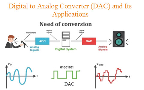
- A/D Converter (ADC): यह एक एनालॉग सिग्नल को डिजिटल सिग्नल में बदलता है।
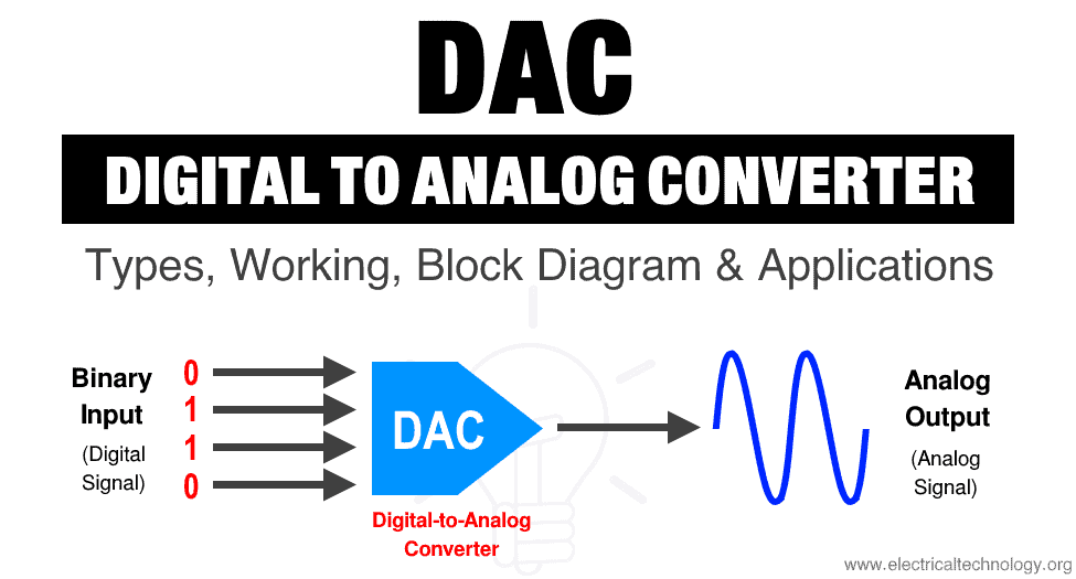
- D/A Converter (DAC): यह डिजिटल सिग्नल को एनालॉग सिग्नल में बदलता है।
🎚️ A/D Conversion Techniques (Analog to Digital):
1️⃣ Successive Approximation Type ADC
- तेज और सटीक।
- एक Comparator और DAC का उपयोग करता है।
- हर बिट के लिए तुलना करता है।
2️⃣ Flash ADC (Parallel ADC)
- बहुत तेज़, लेकिन महंगा और जटिल।
- सभी संभावित आउटपुट के लिए एक Comparator होता है।
- उपयोग: हाई-स्पीड सिस्टम में।
3️⃣ Dual Slope ADC
- शुद्धता के लिए अच्छा, लेकिन धीमा।
- इन्टीग्रेशन के सिद्धांत पर आधारित।
- उपयोग: Digital Multimeters में।
4️⃣ Counter Type ADC
- Counter बढ़ता है जब तक Comparator सिग्नल को मैच न कर ले।
- सरल, लेकिन धीमा।
5️⃣ Sigma-Delta ADC
- High-resolution और Noise-tolerant।
- धीरे-धीरे इनपुट को डिजिटल में बदलता है।
🔁 D/A Conversion Techniques (Digital to Analog):
1️⃣ Weighted Resistor DAC
- हर बिट का वजन अलग होता है (MSB से LSB तक)।
- सरल लेकिन बहुत सटीक रेज़िस्टर्स की जरूरत होती है।
2️⃣ R-2R Ladder DAC
- सभी रेज़िस्टर्स का मान केवल R और 2R होता है।
- सरल डिजाइन और अच्छी सटीकता।
📐 DAC और ADC Performance Parameters:
| Parameter | मतलब |
|---|---|
| Resolution | कितने बिट्स का डेटा कन्वर्ट हो सकता है (e.g., 8-bit, 10-bit) |
| Conversion Time | एनालॉग से डिजिटल या डिजिटल से एनालॉग में बदलने का समय |
| Accuracy | आउटपुट कितना सही है |
| Linearity | इनपुट और आउटपुट के बीच संबंध कितना सीधा है |
🔌 Logic Families – TTL, ECL, MOS, CMOS
✅ Logic Families क्या हैं?
- डिजिटल सर्किट में प्रयोग होने वाले लॉजिक गेट्स को बनाने के लिए प्रयोग की जाने वाली टेक्नोलॉजी।
🔷 1. TTL (Transistor-Transistor Logic)
- टेक्नोलॉजी: Bipolar Junction Transistor (BJT)
- फास्ट और विश्वसनीय
Specifications:
| Parameter | TTL |
|---|---|
| Speed | Medium (~10ns) |
| Power | Medium |
| Noise Margin | Moderate |
| Example | 74 Series ICs |
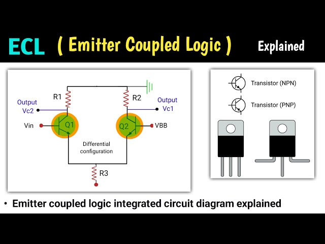
🔷 2. ECL (Emitter Coupled Logic)
- सबसे तेज लॉजिक फैमिली
- ट्रांजिस्टर सैचुरेशन में नहीं जाते
Specifications:
| Parameter | ECL |
|---|---|
| Speed | Very High (<1ns) |
| Power | High |
| Noise Margin | Low |
| Application | हाई-स्पीड कंप्यूटिंग (सुपर कंप्यूटर आदि) |
🔷 3. MOS (Metal Oxide Semiconductor)
- कम पावर कंजम्प्शन
- स्लो स्पीड
Specifications:
| Parameter | MOS |
|---|---|
| Speed | Low |
| Power | Low |
| Application | Static memory आदि में प्रयोग |
🔷 4. CMOS (Complementary MOS)
- दोनों प्रकार के ट्रांजिस्टर (PMOS + NMOS) प्रयोग करता है।
- बहुत कम पावर, और उच्च नॉइज़ मार्जिन
Specifications:
| Parameter | CMOS |
|---|---|
| Speed | Medium to High |
| Power | Very Low |
| Noise Margin | High |
| Application | मोबाइल, माइक्रोकंट्रोलर, लैपटॉप आदि में |
📊 Logic Family Comparison Table:
| Logic Family | Speed | Power | Noise Margin | Cost |
|---|---|---|---|---|
| TTL | Medium | Medium | Medium | Moderate |
| ECL | Very High | High | Low | Expensive |
| MOS | Low | Low | Low | Low |
| CMOS | Medium-High | Very Low | High | Low |
📌 निष्कर्ष:
- ADC/DAC का प्रयोग Real World Analog Signals को Digital Form में लाने/ले जाने के लिए होता है।
- Logic Families का चुनाव system की जरूरत (Speed, Power, Cost) के आधार पर होता है।
Here’s a brief discussion on each topic from the image:
1. A/D and D/A Conversion Techniques
These conversions are essential for interfacing analog signals with digital systems.
A/D (Analog to Digital) Conversion Techniques
- Successive Approximation ADC: Fast and widely used in microcontrollers.
- Flash ADC: Very fast but requires many comparators.
- Dual Slope ADC: Used in digital multimeters for high accuracy.
- Sigma-Delta ADC: Used in high-resolution applications like audio processing.
D/A (Digital to Analog) Conversion Techniques
- Binary Weighted Resistor DAC: Simple but requires precision resistors.
- R-2R Ladder DAC: Most commonly used due to accuracy and ease of implementation.
2. Logic Families and Their Operation
Logic families are groups of electronic logic gates built using similar technologies.
Types of Logic Families
- TTL (Transistor-Transistor Logic)
- Fast and widely used in microprocessors.
- Example: 7400 series ICs.
- ECL (Emitter-Coupled Logic)
- Extremely fast but consumes high power.
- Used in high-speed computing and communication systems.
- MOS (Metal-Oxide Semiconductor Logic)
- Low power consumption, used in large-scale integration (LSI) circuits.
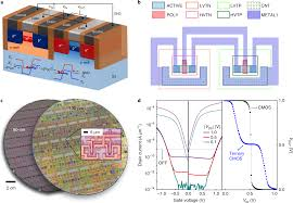
- CMOS (Complementary Metal-Oxide Semiconductor)
- Extremely low power consumption and high noise immunity.
- Used in modern processors and memory devices.
These concepts are fundamental in digital electronics, microprocessor design, and embedded systems. Let me know if you need further clarification! 🚀