🧠 Overview
Computer Architecture defines the design behaviors visible to software—Instruction Set Architecture (ISA), addressing modes, data types, and functional performance optimizations
Computer Organization (Microarchitecture) covers how the architecture is implemented: CPU datapaths, control logic, memory subsystems, I/O controllers, and control signals
⚙️ Key Components
1. Instruction Set Architecture (ISA)
- The interface between hardware and software—defines instruction types (arithmetic, logic, memory, I/O, control)
- Defines addressing modes: direct, indirect, PC-relative, stack-based
- RISC vs. CISC trade-offs: RISC has simple instructions, pipelining‑friendly; CISC has complex instructions
2. Processor & Datapath
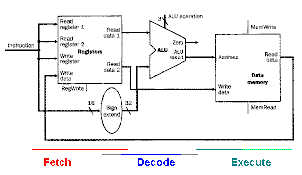
- Instruction cycle: fetch → decode → execute
- Control Unit (CU) orchestrates CPU operations; ALU performs arithmetic/logical tasks; AGU(Address Generation Unit) calculates memory addresses; MMU(Memory Management Unit) handles virtual memory and protection
3. Memory Hierarchy:
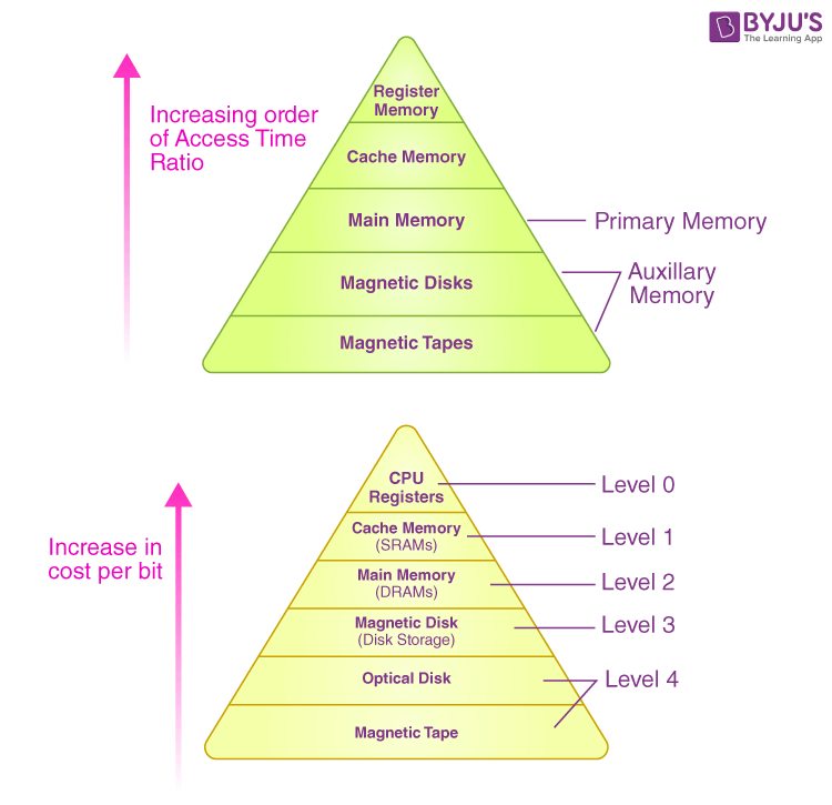
- Multi-level storage: registers → cache → main RAM → secondary storage → tertiary (e.g. tape)
- Caching strategies, mapping, hit/miss penalties; virtual memory and page tables
4. System Organization & I/O
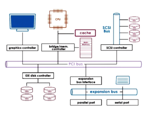
- Device controllers with buffers, interrupt-driven I/O
- Bus architecture connecting CPU, memory, I/O devices.
5. Architectural Models
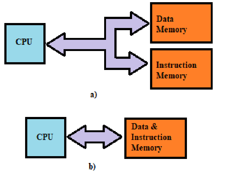
- Von Neumann architecture: unified program/data memory; bottleneck due to shared bus
- Harvard architecture: separate instruction and data memories, used in embedded systems
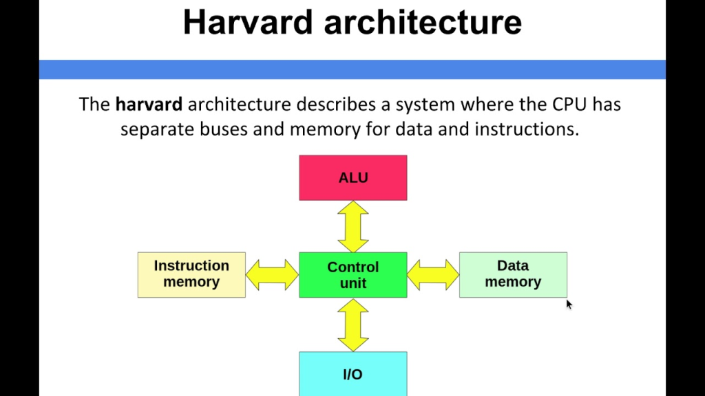
Harvard V/s Von Neuman :-
6. Microarchitectural Enhancements
- Pipelining: breaks instruction execution into stages for parallelism
- Superscalar, out-of-order execution, branch prediction (advanced pipelines).
- RISC benefits from simplified pipelining
Introduction to Data Representation and Number System: Introduction to Decimal, Binary, Octal, Hexadecimal number system, Conversation of number from one number system to another number system (like Decimal to Binary etc.),
Binary Arithmetic: – Addition (Simple Method, Using 1’s Complement, Using 2’sComplement method), Subtraction (Simple Method), Multiplication (Simple Method), Division (Simple Method)
🔢 Number System (संख्या पद्धति) का परिचय:
1️⃣ Decimal Number System (दशमलव संख्या पद्धति):
- आधार (Base): 10
- अंक: 0-9
- उदाहरण: 245₁₀
2️⃣ Binary Number System (बाइनरी संख्या पद्धति):
- आधार: 2
- अंक: 0 और 1
- उदाहरण: 1011₂
3️⃣ Octal Number System (ऑक्टल):
- आधार: 8
- अंक: 0 से 7
- उदाहरण: 57₈
4️⃣ Hexadecimal Number System (हेक्साडेसीमल):
- आधार: 16
- अंक: 0–9 और A–F (जहाँ A=10, B=11…F=15)
- उदाहरण: 3F₁₆
🔄 Number System Conversion (रूपांतरण):
🔁 Decimal → Binary:
- भाग देकर रूपांतरण
- जैसे: 13₁₀ → 1101₂
🔁 Binary → Decimal:
- पोजिशन वैल्यू जोड़कर
- जैसे: 1101₂ → 1×8 + 1×4 + 0×2 + 1×1 = 13₁₀
🔁 Binary → Octal:
- 3-बिट के ग्रुप बनाओ
- 110110 → 110 110 → 6 6 → 66₈
🔁 Binary → Hexadecimal:
- 4-बिट के ग्रुप बनाओ
- 11011110 → 1101 1110 → D E → DE₁₆
(बाकी सभी रूपांतरण इन्हीं नियमों से किये जाते हैं।)
➕ Binary Arithmetic (बाइनरी अंकगणित):
✅ 1. Addition (जोड़)
| A | B | Sum | Carry |
|---|---|---|---|
| 0 | 0 | 0 | 0 |
| 0 | 1 | 1 | 0 |
| 1 | 0 | 1 | 0 |
| 1 | 1 | 0 | 1 |
🔸 Example:
  1011
+ 0101
= 10000
✅ 2. Subtraction (घटाव)
Simple Method with Borrow
| A | B | Difference | Borrow |
|---|---|---|---|
| 0 | 0 | 0 | 0 |
| 1 | 0 | 1 | 0 |
| 1 | 1 | 0 | 0 |
| 0 | 1 | 1 | 1 |
🔸 Example:
  1010
- 0101
= 0101
✅ 3. 1’s Complement Method से Subtraction
Step:
- घटाने वाले (subtrahend) का 1’s complement लो।
- उसे जोड़ो।
- अगर carry आए, तो उसे final answer में जोड़ दो।
✅ 4. 2’s Complement Method से Subtraction
Step:
- Subtrahend का 2’s complement लो (1’s complement + 1)
- उसे minuend में जोड़ो
- Carry ignore करो अगर signed result चाहिए
✅ 5. Binary Multiplication (गुणा)
Same as decimal method:
  101
×  11
-----
  101   (101 × 1)
+1010   (101 × 1, shift 1 place)
-----
 1111
✅ 6. Binary Division (भाग)
Same as long division in decimal:
1011 ÷ 10 = 101 (Binary 11 ÷ 2 = 5)
📘 संक्षेप में:
| टॉपिक | विशेषताएँ |
|---|---|
| Decimal | Base 10, मानव द्वारा प्रयोग |
| Binary | Base 2, कंप्यूटर द्वारा प्रयोग |
| Conversion | Divide/Multiply & Grouping techniques |
| Binary Arithmetic | जोड़, घटाव, गुणा, भाग बाइनरी में |
✅ Main Concepts Explained Simply
1. 🔢 Number Systems
These are different ways to write numbers. Computers use several number systems.
| Number System | Base | Digits Used | Example |
|---|---|---|---|
| Decimal | 10 | 0–9 | 245 |
| Binary | 2 | 0, 1 | 1011 |
| Octal | 8 | 0–7 | 73₈ = 01111011₂ |
| Hexadecimal | 16 | 0–9, A–F | A5 = 165₁₀ |
2. 🔁 Conversions Between Number Systems
You can convert numbers from one system to another.
Examples:
- Decimal to Binary: Divide by 2, write remainders bottom to top
13₁₀ = 1101₂ - Binary to Decimal: Multiply bits by powers of 2
1101₂ = 1×8 + 1×4 + 0×2 + 1×1 = 13₁₀ - Binary to Octal: Group 3 bits from right
110101₂ → 110 101 → 6 5 → 65₈ - Binary to Hex: Group 4 bits from right
11010110₂ → 1101 0110 → D6₁₆
3. ➕➖ Binary Arithmetic
✅ Binary Addition (Simple)
Follow these rules:
0 + 0 = 0
0 + 1 = 1
1 + 1 = 10 (carry 1)
Example:
  1011
+ 1101
------
11000
➖ Binary Subtraction
Simple Method: Like decimal subtraction but with 0s and 1s.
1’s Complement Method:
- Find 1’s complement (flip 0 ↔ 1)
- Add it to the other number
- Add carry if exists
2’s Complement Method:
- Find 2’s complement of subtracted number (flip bits + 1)
- Add to the other number
- If overflow, ignore extra bit
✔️ Most used in computers because it’s faster and easier for subtraction.
4. ✖️ Binary Multiplication (Simple)
Just like decimal multiplication, but:
- Multiply each digit
- Shift left for each row
Example:
   101 (5)
x   11 (3)
-------
   101   (101 × 1)
+ 1010   (101 × 1, shifted)
-------
  1111   (15)
5. ➗ Binary Division (Simple)
Like long division:
- Subtract multiples of the divisor from the dividend
- Bring down bits as needed
Example:
110 ÷ 10 = 11 (6 ÷ 2 = 3)
📌 Summary Table
| Concept | Key Idea |
|---|---|
| Decimal | Base 10 – used in daily life |
| Binary | Base 2 – used in computers |
| Conversion | Change from one number system to another |
| Binary Addition | 1+1 = 10 (carry) |
| Binary Subtraction | Use complements for faster results |
| Binary Multiplication | Shift & add |
| Binary Division | Like long division in binary |
🧠 Tip to Remember
- Binary is base 2, just 0 and 1.
- Use complements to simplify subtraction.
- Group bits to switch between binary ↔ octal/hex easily.
Different Codes Representation of Error Detection Codes: Parity Bit Method, Checksum Method, Representation of Error Correction Code: Hamming Code, Alphanumeric Codes: ASCII, EBCDIC, Excess – 3 Code, BCD Addition Method, Gray Code: Gray to Binary Conversion, Binary to Gray Conversion
🛠️ Error Detection Codes (त्रुटि पहचान कोड)
1️⃣ Parity Bit Method (पैरिटी बिट विधि)
- डेटा के हर समूह में 1 बिट जोड़ी जाती है ताकि बिट्स की संख्या even या odd रहे।
- Even Parity: बिट्स की संख्या हमेशा सम (even) होती है।
- Odd Parity: बिट्स की संख्या विषम (odd) होती है।
- अगर डेटा ट्रांसमिशन में कोई बिट उलट जाए तो parity बदल जाती है और error पता चल जाता है।
2️⃣ Checksum Method (चेकसम विधि)
- डेटा के समूह का योग निकाला जाता है और उसे साथ में भेजा जाता है।
- रिसीवर पर भी यही गणना की जाती है, और अगर चेकसम मैच नहीं करता तो error है।
- सामान्यतः नेटवर्क ट्रांसमिशन में उपयोग।
🛠️ Error Correction Codes (त्रुटि सुधार कोड)
3️⃣ Hamming Code (हैमिंग कोड)
- त्रुटि पहचान और सुधार दोनों कर सकता है।
- डेटा बिट्स के बीच कुछ parity बिट्स डालकर काम करता है।
- यदि एक बिट गलती से बदल जाए तो इसे पहचान कर सही कर सकता है।
- उदाहरण: 7-बिट डेटा में 4 डेटा बिट्स और 3 parity बिट्स।
🔤 Alphanumeric Codes (अल्फान्यूमेरिक कोड)
4️⃣ ASCII (American Standard Code for Information Interchange)
- 7 या 8 बिट का कोड।
- कंप्यूटर में टेक्स्ट के अक्षरों, नंबरों और कंट्रोल कैरेक्टर्स का प्रतिनिधित्व।
- उदाहरण: A = 65 (01000001)
5️⃣ EBCDIC (Extended Binary Coded Decimal Interchange Code)
- IBM द्वारा विकसित 8-बिट कोड।
- मुख्यतः बड़े सिस्टम में उपयोग।
🔢 Number & Special Codes
6️⃣ Excess-3 Code
- BCD (Binary Coded Decimal) का एक संशोधित रूप।
- हर दशमलव अंक में 3 जोड़कर उसका 4-बिट बाइनरी कोड बनाते हैं।
- उपयोग: कुछ कैलकुलेटरों में।
7️⃣ BCD Addition Method (BCD जोड़ विधि)
- दशमलव संख्याओं को 4-बिट बाइनरी में रिप्रेजेंट करते हैं।
- दो BCD नंबर जोड़ते समय यदि परिणाम 9 से बड़ा होता है तो 6 जोड़कर सही BCD रिजल्ट पाया जाता है।
8️⃣ Gray Code
- एक ऐसा बाइनरी कोड जिसमें एक बिट ही बदलता है जब एक नंबर से अगले नंबर पर जाएं।
- उपयोग: एन्कोडर्स, रोटेशन सेंसर आदि में।
🔄 Conversion:
- Binary से Gray Conversion:
- पहला बिट समान रहता है।
- बाद के बिट्स को अपने पिछले बिट के साथ XOR करो।
- Gray से Binary Conversion:
- पहला बिट समान रहता है।
- अगले बिट्स को पिछले बाइनरी बिट के साथ XOR करो।
उदाहरण:
| Decimal | Binary | Gray Code |
|---|---|---|
| 0 | 0000 | 0000 |
| 1 | 0001 | 0001 |
| 2 | 0010 | 0011 |
| 3 | 0011 | 0010 |
संक्षेप:
| कोड | उद्देश्य | विशेषता |
|---|---|---|
| Parity Bit | Error Detection | Simple, 1-bit error detect |
| Checksum | Error Detection | Data blocks के लिए |
| Hamming Code | Error Correction | 1-bit error correct |
| ASCII | Character Encoding | Standard text code |
| EBCDIC | Character Encoding | IBM mainframe use |
| Excess-3 | Decimal Code | BCD के लिए alternative |
| BCD Addition | Decimal Arithmetic | Carry correction |
| Gray Code | Error Reduction | 1-bit difference |
✅ Main Concepts Explained Simply
1. 🔤 Different Codes in Digital Systems
These are ways to represent data (letters, numbers, etc.) in binary so computers can understand it.
➤ Alphanumeric Codes
Used to represent letters and symbols:
- ASCII (American Standard Code for Information Interchange)
- 7-bit or 8-bit codes
- Example: ‘A’ = 65 = 1000001
- EBCDIC (Extended Binary Coded Decimal Interchange Code)
- 8-bit code used by IBM
- Less common than ASCII
2. 💾 BCD (Binary Coded Decimal)
- Represents each decimal digit using 4 bits
- Example:
29 in BCD = 0010 1001 - BCD Addition: When adding, if the result > 9 (1001), add 6 (0110) to adjust.
3. ➕ Excess-3 Code
- Adds 3 to each BCD digit
- Used in error detection and decimal correction
- Example:
Decimal 4 → BCD = 0100 → Excess-3 = 0100 + 0011 = 0111
4. 🎯 Gray Code
- Special binary code where only one bit changes at a time
- Useful in mechanical systems (e.g., position sensors)
✅ Gray ↔ Binary Conversion:
- Binary → Gray:
First bit is same, then each bit = previous binary bit XOR current binary bit - Gray → Binary:
First bit is same, then each binary bit = previous binary bit XOR current gray bit
5. 🛡️ Error Detection Codes
Used to detect mistakes during data transmission.
🔸 Parity Bit Method
- Adds an extra bit to make the total number of 1s either:
- Even (Even Parity) or
- Odd (Odd Parity)
- Can detect single-bit errors
🔸 Checksum Method
- Break data into blocks, add them, and send the sum (checksum)
- Receiver adds blocks again to verify
- Used in networks and files
6. 🛠️ Error Correction Code
🔸 Hamming Code
- Detects and corrects 1-bit errors
- Uses parity bits at power-of-2 positions
- Can locate and fix the exact error bit
🧠 Quick Summary Table
| Concept | What It Does | Use Case |
|---|---|---|
| ASCII / EBCDIC | Stores characters as binary | Text in computers |
| BCD | Stores decimal digits in binary | Calculators, digital clocks |
| Excess-3 Code | Error-friendly decimal code | Arithmetic circuits |
| Gray Code | Changes only one bit at a time | Mechanical sensors |
| Parity Bit | Detects 1-bit error | Simple transmission check |
| Checksum | Detects block errors | Networking, file transfer |
| Hamming Code | Finds & fixes 1-bit error | Memory systems, data transfer |
Introduction to Ideal Microcomputer, An Actual Microcomputer: CPU, Address Bus, Data Bus, Control Bus, Memory: RAM – SRAM, DRAM, ROM – PROM, EPROM, UVEPROM, EEPROM, History of Microprocessor, Microcontroller (Application Only), Addressing Techniques, Introduction To Digital Electronics, Logic Gates: Inverter, OR Gate, AND Gate, NOR Gate, NAND Gate, EX-OR Gate, EX-NOR Gate, De’Morgan’s Theorems
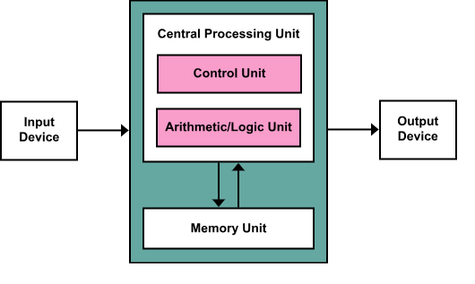
🖥️ Introduction to Ideal Microcomputer (आदर्श माइक्रोकंप्यूटर का परिचय)
- Ideal Microcomputer एक परफेक्ट या सिद्धांत आधारित कंप्यूटर होता है जिसमें सभी कंपोनेंट बिना किसी त्रुटि और पूरी दक्षता के काम करते हैं।
- इसमें CPU, Memory, Input/Output Devices आदि होते हैं।
🖥️ An Actual Microcomputer (वास्तविक माइक्रोकंप्यूटर):
मुख्य घटक (Components):
- CPU (Central Processing Unit)
- कंप्यूटर का दिमाग, जो सारे काम और कंट्रोल करता है।
- Address Bus (एड्रेस बस)
- CPU से मेमोरी तक पता (address) भेजता है कि कौन-सी लोकेशन पढ़नी या लिखनी है।
- यह केवल एक दिशा में डेटा भेजता है।
- Data Bus (डेटा बस)
- CPU और मेमोरी या I/O डिवाइस के बीच डेटा ट्रांसफर करता है।
- यह दो-तरफा होता है।
- Control Bus (कंट्रोल बस)
- CPU के निर्देशों के अनुसार मेमोरी और I/O को नियंत्रित करता है, जैसे रीड या राइट करना।
💾 Memory Types (मेमोरी के प्रकार):
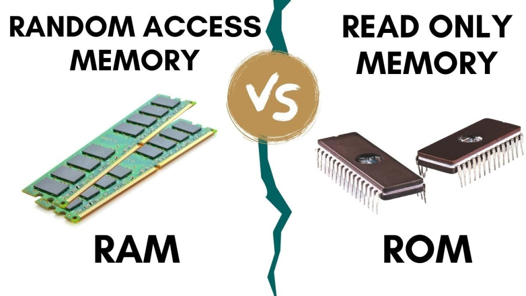
- RAM (Random Access Memory)
- अस्थायी मेमोरी, डेटा को रीड और राइट दोनों कर सकते हैं।
- मुख्यतः प्रोग्राम और डेटा स्टोर करता है।
2. SRAM (Static RAM):
- तेज़, महंगा, पावर ज्यादा खपत करता है, कैश मेमोरी में इस्तेमाल।
3. DRAM (Dynamic RAM):
- धीमा, सस्ता, पावर कम खपत करता है, मुख्य मेमोरी में।
4. ROM (Read Only Memory)
- केवल पढ़ा जा सकता है, न लिखा।
- सिस्टम स्टार्टअप कोड जैसे BIOS होता है।
- PROM (Programmable ROM):
- EPROM (Erasable Programmable ROM):
- यूवी लाइट से डेटा मिटाकर दोबारा प्रोग्राम किया जा सकता है।
- UVEPROM:
- EPROM का एक प्रकार जो UV लाइट से मिटाया जाता है।
- EEPROM (Electrically Erasable Programmable ROM):
- इलेक्ट्रिकली मिटा और प्रोग्राम किया जा सकता है, फ्लैश मेमोरी में इस्तेमाल।
🕰️ History of Microprocessor (माइक्रोप्रोसेसर का इतिहास):
- 1971 में Intel ने पहला माइक्रोप्रोसेसर 4004 लॉन्च किया।
- तब से माइक्रोप्रोसेसर की क्षमता, गति और कम ऊर्जा खपत लगातार बढ़ी।
🔧 Microcontroller (माइक्रोकंट्रोलर) (Application Only)
- माइक्रोकंट्रोलर एक छोटा कंप्यूटर होता है जिसमें CPU, मेमोरी और I/O पोर्ट्स एक ही चिप में होते हैं।
- इस्तेमाल: घरेलू उपकरण, ऑटोमोटिव, इंडस्ट्रियल कंट्रोल, रोबोटिक्स।
🎯 Addressing Techniques (एड्रेसिंग तकनीकें):
- CPU मेमोरी या डेटा तक पहुँचने के लिए कई तरीके अपनाता है:
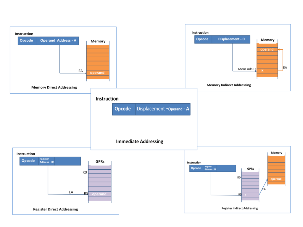
- Immediate Addressing: डेटा CPU के अंदर ही होता है।
- Direct Addressing: मेमोरी से सीधे पता देकर डेटा लिया जाता है।
- Indirect Addressing: मेमोरी में पते का पता किसी अन्य पते पर होता है।
- Indexed Addressing: बेस एड्रेस + इंडेक्स रजिस्टर के जरिए पता।
⚡ Introduction to Digital Electronics (डिजिटल इलेक्ट्रॉनिक्स का परिचय):
- डिजिटल इलेक्ट्रॉनिक्स में केवल दो स्टेट्स होते हैं: 0 और 1।
- कंप्यूटर और डिजिटल डिवाइसेज इन्हीं 0 और 1 के साथ काम करते हैं।
🔲 Logic Gates (लॉजिक गेट्स):
- ये डिजिटल सर्किट के बेसिक बिल्डिंग ब्लॉक्स हैं।
| Gate | Symbol | Operation | Truth Table Example |
|---|---|---|---|
| Inverter (NOT) | ¬A | Output = Opposite of input | A=0 → Y=1, A=1 → Y=0 |
| AND Gate | A·B | Output = 1 जब दोनों 1 हों | 1 AND 1 = 1 |
| OR Gate | A + B | Output = 1 जब कोई एक 1 हो | 0 OR 1 = 1 |
| NAND Gate | ¬(A·B) | AND का उल्टा (NOT AND) | 1 NAND 1 = 0 |
| NOR Gate | ¬(A + B) | OR का उल्टा (NOT OR) | 0 NOR 0 = 1 |
| EX-OR Gate | A ⊕ B | Output = 1 जब अलग-अलग हों | 1 XOR 0 = 1 |
| EX-NOR Gate | ¬(A ⊕ B) | EX-OR का उल्टा | 1 XNOR 1 = 1 |
📐 De Morgan’s Theorems (डी मॉर्गन के नियम):
- लॉजिक गेट्स के नियम जो कंप्लेक्स एक्सप्रेशंस को सरल बनाते हैं:
- (A·B)’ = A’ + B’
(AND का NOT = OR के NOT का योग) - (A + B)’ = A’·B’
(OR का NOT = AND के NOT का गुणन)
इसे याद रखने के लिए:
- NOT(AND) = OR(NOT)
- NOT(OR) = AND(NOT)
✅ Easy Explanation of Key Concepts
🖥️ Microcomputer Basics
✅ Ideal vs Actual Microcomputer
- Ideal Microcomputer: A theoretical model with all basic parts (CPU, memory, input/output, etc.)
- Actual Microcomputer: Real systems like desktops or embedded devices
🔧 Components:
- CPU (Central Processing Unit) – The brain; processes instructions
- Address Bus – Tells where to find/store data
- Data Bus – Carries actual data
- Control Bus – Sends control signals (like read/write commands)
💾 Memory Types
| Type | Description |
|---|---|
| RAM | Temporary memory; loses data when power is off |
| → SRAM | Fast, expensive, used in cache |
| → DRAM | Slower, cheaper, used in main memory |
| ROM Type | Description |
|---|---|
| ROM | Read-Only Memory; permanent storage |
| PROM | Programmable once |
| EPROM | Erasable with UV light |
| UVEPROM | Same as EPROM (UV = ultraviolet) |
| EEPROM | Electrically erasable and reprogrammable |
🧠 Microprocessor & Microcontroller
- Microprocessor: A chip that only contains the CPU
(needs extra chips for memory, I/O) - Microcontroller: All-in-one chip (CPU + memory + I/O)
Used in washing machines, TV remotes, etc.
📍 Addressing Techniques
How instructions refer to memory locations:
- Immediate: Data is part of the instruction
- Direct: Address is given directly
- Indirect: Address points to another address
- Indexed: Uses base address + offset
💡 Digital Electronics Basics
🔌 Logic Gates – Building blocks of digital circuits:
| Gate | Symbol | Output Rule |
|---|---|---|
| NOT (Inverter) | ¬A or A̅ | Opposite of input |
| OR | A + B | 1 if any input is 1 |
| AND | A • B | 1 if both inputs are 1 |
| NOR | ¬(A + B) | 1 if all inputs are 0 |
| NAND | ¬(A • B) | 0 only if all inputs are 1 |
| XOR | A ⊕ B | 1 if inputs are different |
| XNOR | ¬(A ⊕ B) | 1 if inputs are same |
📐 De Morgan’s Theorems
These help simplify logic expressions:
- ¬(A + B) = ¬A • ¬B
- ¬(A • B) = ¬A + ¬B
Used in logic gate design and Boolean algebra.
📌 Summary Table
| Concept | Key Point |
|---|---|
| Microcomputer | Includes CPU, memory, I/O |
| RAM vs ROM | RAM is temporary, ROM is permanent |
| Microcontroller | All-in-one chip (used in gadgets) |
| Logic Gates | Perform basic logical operations |
| De Morgan’s Theorems | Used to simplify logic expressions |
Universal Gates (Only for Logic Conversion), K-Map Simplifications, Pair, Quad, Octet (upto 4 variables) Don’t Care Condition, Arithmetic Logic Unit: Half Adder, Full Adder, Binary Adder,2’s Complement Adder Subtractor
🔄 Universal Gates (सर्वजन्य गेट्स)
- Universal gates वो लॉजिक गेट्स होते हैं जिनसे कोई भी दूसरे लॉजिक गेट्स (AND, OR, NOT) बनाए जा सकते हैं।
- दो प्रमुख Universal gates हैं:
- NAND Gate
- NOR Gate
NAND से लॉजिक गेट बनाना:
- NOT = NAND gate में दोनों इनपुट same दें
- AND = NAND के आउटपुट को फिर NAND से invert करें
- OR = NAND के इनपुट को invert करके फिर NAND करें
NOR से लॉजिक गेट बनाना:
- NOT = NOR gate में दोनों इनपुट same दें
- OR = NOR के आउटपुट को फिर NOR से invert करें
- AND = NOR के इनपुट को invert करके फिर NOR करें
📊 K-Map Simplifications (कर्नोमैप सरलीकरण)
- K-Map (Karnaugh Map) एक टूल है जो लॉजिक एक्सप्रेशन को आसान (simplify) बनाने में मदद करता है।
- इसमें Truth Table को ग्रिड फॉर्म में व्यवस्थित किया जाता है।
- ग्रुपिंग से हम एक्सप्रेशन को SOP (Sum of Products) या POS (Product of Sums) फॉर्म में कम टर्म्स में लिख सकते हैं।
Grouping Types:
- Pair (2 adjacent 1’s)
- Quad (4 adjacent 1’s)
- Octet (8 adjacent 1’s) — 4 वेरिएबल तक काम आता है।
Don’t Care Condition:
- जब कुछ इनपुट्स की वैल्यू कोई फर्क नहीं डालती, उन्हें ‘X’ या don’t care कहा जाता है।
- Don’t care को 1 या 0 की तरह गिना जा सकता है जिससे सरलीकरण आसान हो जाता है।
➕➖ Arithmetic Logic Unit (ALU)
Half Adder (हाफ़ एडर):
- दो बिट्स को जोड़ता है।
- आउटपुट: Sum और Carry
- Sum = A XOR B
- Carry = A AND B
| A | B | Sum | Carry |
|---|---|---|---|
| 0 | 0 | 0 | 0 |
| 0 | 1 | 1 | 0 |
| 1 | 0 | 1 | 0 |
| 1 | 1 | 0 | 1 |
Full Adder (फुल एडर):
- तीन बिट्स जोड़ता है: दो बिट्स और एक Carry इन।
- आउटपुट: Sum और Carry आउट
- Sum = A XOR B XOR Cin
- Carry = (A AND B) OR (B AND Cin) OR (A AND Cin)
Binary Adder (बाइनरी एडर):
- कई फुल एडर्स को जोड़कर बनाया जाता है ताकि मल्टी-बिट बाइनरी नंबर जोड़े जा सकें।
- जैसे 4-bit या 8-bit एडर।
2’s Complement Adder-Subtractor (2 का पूरक एडर-सब्ट्रेक्टर):
- 2’s complement बाइनरी संख्या का उपयोग घटाने के लिए किया जाता है।
- Subtraction को Addition में बदलने के लिए 2’s complement ली जाती है।
- ALU में 2’s complement के ज़रिए add और subtract दोनों ऑपरेशन किए जा सकते हैं।